

Can't afford a Big Green Egg? You can build a ceramic smoker from a flowerpot in a matter of minutes — Alton Brown showed how on "Good Eats". Here I show how to add temperature control to your flowerpot smoker so that you can "set it and forget it". With automatic heating you can take the fiddling and guesswork out of using your smoker... and still have an excuse to hang out in the garden drinking beer.

Flowerpot Smoker
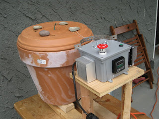
To build the basic smoker you will need a large ceramic flower pot, the largest you can find. The idea of using a flower pot is that the ceramic walls retain moisture as well as heat — which is ideal for slow cooking. You will need a lid for the smoker too: a matching base will do fine, but a ceramic bowl of the right width or duplicate flowerpot turned upside down will allow taller objects on the grate. Prop the flower pot on ceramic feet or otherwise arrange it so that air can come up through the drain hole. Then take a single ring electric burner. Remove the element from its casing and reconnect the spade connectors directly to the electric cord, bypassing the temperature dial. Put the burner in the bottom of the flower pot and feed the cord out of the drain hole. You may need to lay the element on a brick to get it level. Next put a metal tray of wood chips on the burner. A pie pan will do fine, but avoid anything with a nonstick surface. Finally prop a circular BBQ grate inside the flower pot. Watch this video to see the master at work:
Temperature Controller
The heating element will be governed by a PID controller that is connected to a solid state relay (SSR). A PT100 temperature probe measures the temperature inside the flowerpot. Check to see that the controls will fit in a 6" x 6" x 4" PVC junction box. Once you have figured out where everything will go, cut a hole for the SSR heatsink so that it can be mounted on the outside. You will also need to drill or cut holes for the PID panel, a receptacle to plug in the burner, the power cord, a fuse to protect the controller, on/off switches, and the temperature probe. I used separate on and off switches connected via a power relay, but a simple rocker switch will do fine as long as it is rated for 110 V and 15 A. Female and male 3 pin XLR connectors are great for attaching the probe using microphone cable. I recommend protecting the outlet receptacle from the weather with an in-use cover.

To assemble the controller box, use the circuit schematic below (click the picture to make it bigger). If you don't already have them, you will need a soldering iron and a crimper to make the electrical connections and a multimeter to test them. An electric drill will be useful for making holes in the box and attaching screws.

Get Cooking
Put damp wood chips in the pan, slap your favorite cut of meat on the grate, and set the required temperature on the controller. Then sit back until the food is ready. A probe thermometer can be used to monitor the internal temperature of the meat.
Perhaps try customizing the smoker to your personal requirements. A simple way to ventilate the smoker is to drill small holes in the lid using a masonry bit and cover them when necessary with with stones. While you're at it, make another hole for the temperature probe. A handle for the lid is a very useful feature. To make a mobile BBQ station, cut a circular hole in a butcher block using a jigsaw or router and mount the flowerpot inside.
Did you know?
You can also use the PID controller to cook
sous vide using a crockpot or electric kettle.
Safety
Please remember to use mains electricity safely. The controller is designed to provide some protection against the weather, but it is not completely waterproof. Always plug the controller into a GFCI protected receptacle when cooking. Undercooked food can cause illness: calibrate your probe if what you are cooking requires accurate temperature measurement.
Construction tips
This project is one for the Expert. Do not attempt to build the controller unless you can competently wire up mains electricity. The flowerpot smoker itself is easy to assemble but the 110 V supply is potentially Dangerous.
Materials
Flowerpot smoker
- Flower pot (17" diameter, or the largest you can find)
- Flower pot base (fits on top for lid)
- Plumber's strap (for handle)
- Stainless steel bolts, nuts, washers (for handle)
- Circular BBQ grate
- Single ring burner
- Aluminium pan (for wood chips)
PID controller
- Carlon junction box 6" x 6" x 4"
- PID Temperature Controller TD4-SNR and Solid State Relay SSR-25DA
- Heatsink for SSR
- Heatsink compound 30g (way excess)
- High quality waterproof PT100 RTD temperature probe
- XLR 3 pin female chassis mount
- XLR 3 pin male plug
- female to male XLR mic cable
- 15A 125V receptacle
- Weatherproof single outlet cover
- PG11 waterproof gland
- 14/2 AWG SJT electrical cord
- Leviton 15A 125V rubber grounding plug
- Panel mount fuse holder (only 1 needed)
- 250V 1A quick blow fuse
- 660V 10A emergency stop mushroom switch NC
- Waterproof momentary pushbutton switch NO
- DPDT relay, 120V coil, rated 30A
- 12-position 30A terminal block
You will also need
- Soldering iron
- Electrical solder (rosin flux core, lead free)
- 14 AWG wire (for high power connections, rated to 15A)
- 22 AWG hook up wire
- Electric drill
- Screwdrivers
- Nibbling tool (to make holes in junction box)
- Crimper/wire stripper and solderless connector kit
- Silicone sealant
22 comments:
From Alton's video:
> The best thing: I spent exactly $47.32.
Where the heck does he shop?? I couldn't find a terra cotta flower pot that size for less than $50, and that doesn't include the lid. Add in a lid, a new electric burner and a replacement thermonometer, and the bill would have come out to $114.someodd in my area. That didn't even include the pie plate for the wood chips.
I think that video is a few years old now. Home Depot is the cheapest source near me but they don't always have the larger sizes.
I have been looking for a month or so for a PID design that only controls heat. Your design is clean, recent, and well thought out. Anyway you could include a better schematic for people to look at? Even when enlarged its a bit fuzzy.
Thanks
If you have any other pictures of the construction they would be welcomed I'm sure
Thanks Levi! I've updated the schematic, I hope the bigger size is easier to read. I don't have any other pictures of the controller build but I'll see if I can take some shots of inside the flowerpot smoker itself.
A few more shots of the inside of your controller would be more helpful, the smoker construction process is widely found on the internet.
Hi, nice post. I've been thinking about upgrading my smoker to a PI or PID (right now it is on/off with temp sense), as well as build a curing chamber with this sort of temp control. I'm happy to see that these PID controllers can be had for so cheap. Last time I looked into them, I was only searching on one brand that was going for over a hundred dollars.
Question about 2 of your relay connections: Why do you have the output of the over-temp relay connected to two non-coil terminals on that DPDT. This doesn't seem to do anything, but I may be missing something.
Also, what type of switch is that power-reset? Is it a rocker with the other side unused (e.g. essentially SPST)?
Thanks
-Mike
Ok nevermind my two questions. I should have spent another minute or two looking at it. I saw you had "latching" on the DPDT but didn't think it through. So I understand your power-set and reset, and I'm guessing the unused terminals were just what was available on the mushroom switch.
-Mike
Yes, that's right Mike. Some mushroom switches are NC only, but the one I used had terminals for both NO and NC operation.
Tom, I'm not very familiar with EE design and would like to know the values for the resistor and capacitor on the latching relay circuit. If I understand the circuit, when there is an alarm (Overtemp) this circuit will kill the power to the latching relay which in turn kills the power to the heater. This is a great safety feature for very little added circuitry. With the DPDT relay, the line voltage for the heater is separate from the line voltage for the controller and it could be 240VAC if needed for the heater. Should there be a second fuse for this heater line? There is also a resistor in the SSR circuit. What is its value?
William (1) The resistor and capacitor form a snubber circuit intended to help prevent arcing across the relay terminals when switching the latch. I used values of 100 R / 0.5 W and 0.1 uF / 250 VAC. (2) The circuit is designed for 120 VAC operation. To switch 240 VAC a different layout would be needed and I would probably choose a 240 V thermal breaker rather than 2 fuses. (3) The resistor in the SSR circuit is 330 R. It was included as a precaution because no datasheet was available for the SSR that I had.
the good eats episode was from 2003. yeah it cost less then. :P
i bought a 30in pot @ my local home depot last week for summer flowers . was thinking of doing this project this summer with my girlfriend. we're big on pit style slow cooking
That's a good size! I wish mine was bigger.
Just built this with good results. Would like to hear what settings you've used for P, I and D.
Scott
That's great to hear! I just set the controller to auto tune, but I'll have a look at what it comes up with next time I grill something. :)
Tom, is there a clean diagram for your PID? the bigger picture is not clean on my nexus :-) . if there's a link for the diagram can you post.
Thanks.
Yves
Hi Yves, I don't have a smart phone so I am not sure how to help. On my laptop, if you click on the picture you can see it bigger, right click to download.
Tom,thanks for the reply and I did the download of the diagram
months ago and its not clear. I want buy everything and give that for xmas present. So a clear,readable diagram would help.
Thanks,
This looks pretty awesome, I have an electric smoker but this actually looks like a fun project.
Top 5 Best offset smokers for beginners?
Masterbuilt Vertical Smoker (Best Overall)
Pit Boss Pellet Smoker (Best Pellet Grill Option)
Masterbuilt Bullet Smoker (Best Budget Smoker)
Traeger Pro 780 (Best High End Smoker)
Masterbuilt Electric Smoker
film not working
Post a Comment